Designing a bent beam to resist lateral torsional buckling
Introduction
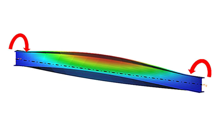
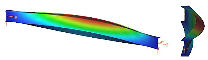
When a beam, bent in a plane, is allowed to move and twist freely between its two support points, in addition to bending, sudden perpendicular displacement and twisting may occur: causing the beam to deviate out of its original plane. This phenomenon is illustrated in Figure 1, showing a single supported beam with I-section bent around the strong axis. As the bending moment in the vertical plane increases, reaching a critical value, the beam undergoes abrupt lateral movement and twisting between the supports. This phenomenon is called lateral torsional buckling (LTB), which is a loss of stability mode that can apply to both perfect beams and real beams.
The design of the beam against LTB is fully analogous to the design of a compressed column against flexural buckling. The analogy is illustrated in Table 1, where the corresponding parameters are shown that affect the two buckling resistances:
| Flexural (column) buckling | Lateral torsional buckling |
|---|---|
| design force ($N_{Ed}$) | design moment ($M_{Ed}$) |
| critical force ($N_{cr}$) | critical moment ($M_{cr}$) |
| column slenderness ($\frac{}{\lambda}$) | beam slenderness ($\frac{}{\lambda}_{LT}$) |
| buckling reduction factor ($\chi$) | buckling reduction factor ($\chi_{LT}$) |
| buckling resistance ($N_{b,Rd}$) | buckling resistance ($M_{b,Rd}$) |
The critical moment of the perfect beam is determined at the location of the maximum value of the My,Ed design bending moment diagram. For a doubly symmetrical I cross-section:
$$M_{cr}=C_1\frac{\pi^2EI_z}{(k_z⋅L)^2}\left[\frac{I_\omega }{I_z}+ \frac{(k_zL)^2GI_t}{\pi^2EI_z}\right] ^{0.5} $$
where kz is the coefficient of restraint about the weak axis of the cross-section, G is the shear modulus, and It and Iω are the pure (St. Venant) and warping torsional moments of inertia of the cross-section. The value of the factor C1 depends on the shape of the bending moment diagram and its value can be found in appropriate tables and manuals. For a constant moment diagram, C1=1.0. The formula for the other design parameters, in particular the buckling reduction factor $\chi_{LT}$, depends on the design standard considered.
Lateral torsional buckling resistance by EN1993-1-1
The design of the beam against LTB (load capacity check) according to EC3-1-1 shall be carried out in the following steps:

Log in to view this content
Online service access and support options are based on subscription plans. Log in to view this content or contact our sales department to upgrade your subscription. If you haven’t tried Consteel yet, try for free and get Pro access to our learning materials for 30 days!