Buckling length of lattice girder bars
Designing a lattice girder
The design of the bars of a truss (lattice girder) structure does not require any special theoretical knowledge: normally, the truss bars are designed as compressed and/or tensioned bars, neglecting bending moments and shear forces. The dimensioning of compression bars is nowadays carried out using a model-based computer procedure. For details, see the knowledge base material Design of columns against buckling. Here, only the determination of the deflection length of the compressed bars is presented.
The most important parameter for the dimensioning of a compressed bar is the slenderness:
$$\frac{}{\lambda}=\sqrt\frac{Af_y}{N_{cr}}$$
where
$$N_{cr}=\frac{\pi^2El}{(kL)^2}$$
where the buckling length factor k is recommended by EN1993-1-1 to facilitate manual calculations:
| Type of the bar | Direction of buckling | k |
|---|---|---|
| chord | - in-plane - out-of-plane | 0.9 0.9 |
| bracing | - in-plane - out-of-plane | 0.9 1.0 |
Software using model-based computational methods (e.g. Consteel software) determines the elastic critical force Ncr directly by finite element numerical methods, taking into account the behaviour of the entire lattice girder, instead of the above conservative formula. The following example is intended to illustrate the relationship between the manual design procedure proposed by the standard and the results of the modern model-based numerical procedure.
- Let the structural model of the lattice girder under consideration be the Consteel model shown in Figure 1.
- Let the load shown correspond to the design load combination of the girder.
- Determine the deflection length of the most stressed compressed chord member using finite element numerical stability analysis.
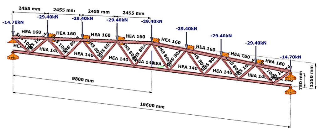
(Consteel software)
Relationship between procedures
The steps of the calculation are:
Buckling stability analysis
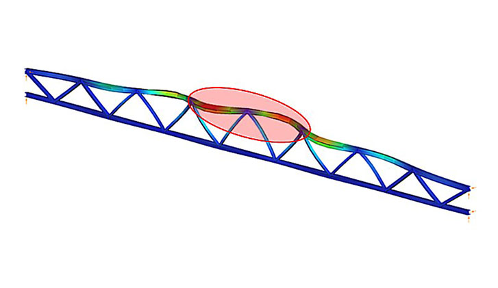
The stability analysis of the elastic model shows the governing buckling mode of the lattice structure and the corresponding elastic critical load factor αcr (Figure 2).
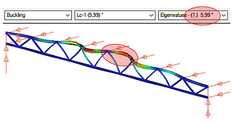
We can see that the upper chord of the perfectly elastic model is deflected laterally under load. The load that causes this elastic buckling is the critical load, whose value is given by the product of the design load and the critical load factor αcr=5.99.

Log in to view this content
Online service access and support options are based on subscription plans. Log in to view this content or contact our sales department to upgrade your subscription. If you haven’t tried Consteel yet, try for free and get Pro access to our learning materials for 30 days!